

Graph Engineering: Designing Agent Systems That Coordinate

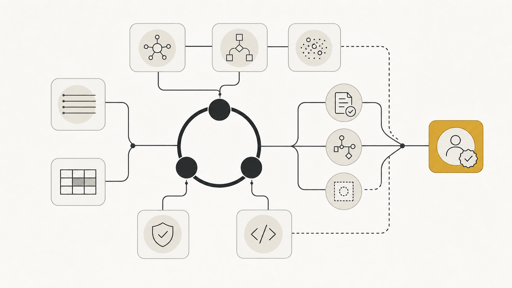 A graph engineering control plane for agent work
One agent can fix a bounded problem. Several agents can still leave a human doing the most consequential work: deciding what starts next, which output is trustworthy, what state crosses a handoff, and when a failure should stop rather than retry.
That is the coordination gap.
The recent conversation around graph engineering is trying to name this layer of system design. The term is fresh and its definition is not settled, but the problem is real. A system with many capable nodes is not reliable merely because it can call more models in parallel. It needs an explicit shape for work, state, evidence, and authority.
Graph engineering is the practice of designing that shape. It turns a collection of agents, tools, evaluators, and humans into an inspectable coordination system.
The important distinction is simple:
Loop engineering designs how a unit of work converges.
Graph engineering designs how many units of work coordinate.
Graphs do not replace loops. A loop is simply a directed graph with a cycle, and production agent graphs commonly need them: retrying failed tool calls, asking for missing information, revising after validation, or pausing for human input. A production graph normally contains several local loops: an implementation loop that repairs a failing test, a research loop that closes an evidence gap, or an operations loop that retries a recoverable action. The graph decides where those loops begin, what they are allowed to change, and who is allowed to declare the wider task complete.
1. The Problem Is Not More Agents. It Is More Relationships.🔗
The first version of an agent system is often a single line of control:
prompt → model → tool → observation → retry
That is enough for a focused task. As work becomes longer-running, teams add a researcher, implementer, reviewer, security check, deployment gate, and human approver. The result is often called “multi-agent,” but that label hides the engineering question.
What does the reviewer receive: a summary, a diff, test output, or the entire history? Can the reviewer send the task back? Can it veto a deployment? If two reviewers disagree, who resolves the conflict? Which data is shared, which data is immutable, and which node owns the final state?
These are graph questions. They are not solved by adding another prompt or asking a supervisor agent to be “careful.”
The term has accelerated in practitioner discussion because builders are encountering this boundary now. The architecture itself is older: LangChain describes LangGraph as three years of work on representing agentic systems as graphs. Recent explainers disagree on the vocabulary but converge on the useful distinction: a loop governs local feedback; a graph makes dependencies, branches, joins, and escalation paths explicit. That framing is a better starting point than the claim that one pattern has made another obsolete.
2. A Precise Vocabulary🔗
Before drawing an architecture, separate four things that are regularly collapsed into the word “agent.”
| Term | What it is | Question it answers |
|---|---|---|
| Agent | A probabilistic actor that interprets context and proposes actions | What could happen next? |
| Node | Any work unit: an agent, deterministic function, evaluator, or human gate | Who or what performs this responsibility? |
| Loop | A bounded feedback cycle with a goal, evidence, budget, and stop rule | How does this work unit converge? |
| Graph | The topology of nodes, transitions, state, dependencies, and authority | How does the system coordinate work? |
| Governor | The owner of a decision when nodes disagree or risk is high | Who has the authority to resolve this? |
Not every node should be an agent. Routing, schema validation, permissions, idempotency checks, joins, and budget enforcement are usually better as deterministic software. They are faster, cheaper, easier to test, and less likely to invent a reason to proceed.
This is the first discipline of graph engineering: draw boundaries around responsibilities, not around models. A node deserves to exist when it has a distinct objective, permission set, input/output contract, or independent verifier.
3. A Graph Is More Than a Flowchart🔗
Every workflow can be drawn as boxes and arrows. That does not make it engineered.
An engineering graph gives every arrow operational meaning. An edge is not simply “then.” It is a contract that states:
- the structured state moving to the next node;
- the evidence required for the transition;
- the owner permitted to update that state;
- the route type: success, retry, branch, join, stop, or escalation; and
- the budget, timeout, and permissions inherited by the destination.
Consider the difference between these two handoffs:
Researcher → Implementer
Researcher → Implementer
input: { verified_constraints, source_links, acceptance_tests }
transition only when: each constraint has provenance
authority: implementer may modify code, not acceptance tests
budget: one branch, 30 minutes, no deploy permission
The first is a diagram. The second is a control boundary.
This is familiar terrain in distributed systems: interfaces, ownership, retries, and failure semantics determine whether components compose. Agent systems need the same discipline, with one extra complication: some nodes are probabilistic and will confidently misread an ambiguous handoff.
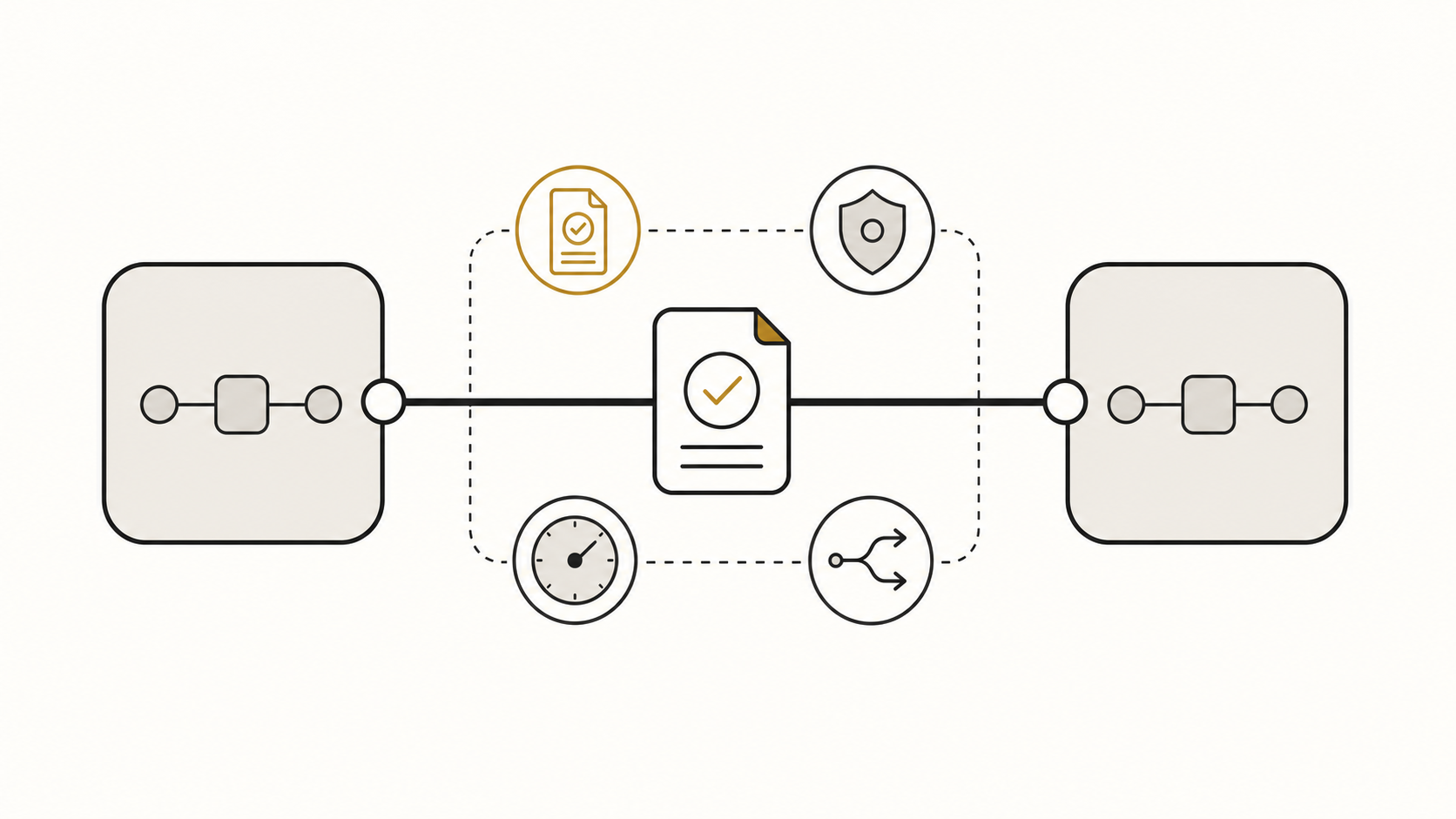 An edge contract carries evidence, authority, routing, and budget between work nodes
4. The Five Objects to Design🔗
4.1 Node boundary
Each node should own one coherent responsibility. A research node gathers and normalizes evidence. An implementation node produces a candidate change. A verifier evaluates the artifact against an independent check. A human gate approves an irreversible action.
Avoid role names that hide ownership. “Planner,” “worker,” and “critic” sound useful but do not explain what a node can read, change, or approve. Prefer boundaries grounded in a real artifact and permission: triage incident, extract source-backed claims, run migration in a sandbox, approve production deployment.
4.2 State schema
The central design problem in multi-node work is not the model. It is shared state.
Giving every agent the same global conversation history seems convenient, but it creates context bloat, accidental coupling, and unclear ownership. One node’s speculative note becomes another node’s assumed fact. Parallel nodes overwrite each other. A failed branch leaves behind state that looks complete.
Use a typed state schema instead. Separate:
- facts — tool-produced observations with source and timestamp;
- proposals — model-generated plans, changes, and explanations;
- decisions — accepted transitions with the responsible authority;
- artifacts — diffs, reports, test output, and identifiers; and
- budgets — time, spend, retries, and permission scope.
For consequential systems, an append-only evidence ledger is often safer than mutable shared memory. Nodes can add evidence; a governor or deterministic reducer decides what changes the accepted state. This makes a workflow inspectable after the fact.
4.3 Edge contract
Edges are where assumptions become failures. Define their preconditions explicitly.
An implementation node should not start merely because a researcher says “ready.” It should start when a structured evidence bundle exists, its required fields validate, and the task is within its authority. A verification node should not pass an artifact because the implementer reports success; it should pass only when the relevant checks produce evidence.
Treat an agent’s “done” as a proposed transition, never as proof that the state is done.
4.4 Routing policy
Graph engineering makes routes first-class:
- success: evidence satisfies the next node’s contract;
- retry: a recoverable failure has new information and remaining budget;
- return: an evidence gap sends work back to the node that can close it;
- fan-out: independent checks may proceed in parallel;
- join: parallel results merge only under defined conflict rules;
- escalate: risk, ambiguity, or exhausted budget transfers authority to a human; and
- stop: the system reaches a verified terminal state.
The word “new” matters in retries. A loop that repeats the same prompt against the same failure is not self-correcting; it is a billing mechanism. Require a new observation, changed state, or explicit strategy before permitting another attempt.
4.5 Authority and escalation
Topology does not create permission. An arrow can show that the security reviewer may receive a diff; it does not say whether the reviewer can block a merge. That must be designed.
Every graph needs a Governor to answer four questions:
- Who owns the goal and its acceptance criteria?
- Which nodes may modify which artifacts?
- Which node can invalidate a previous result?
- Who resolves conflicts and approves irreversible actions?
The answer may be a human operator, a service owner, a policy engine, or a designated approval node. What matters is that it is explicit. Without a governor, a graph can manufacture the appearance of consensus while no one has actually made the decision.
5. A Reference Graph for Software Delivery🔗
Consider a change request that affects a production service. A reliable graph could contain:
Intake → Triage → Investigate → Implement ⇄ Test / repair → Independent verification
                                               │                    │
                                               └── evidence gap ────┘
                                                                    ├── pass → Review → merge gate → done
                                                                    └── risk or conflict → human governor
The implementation loop is intentionally local. It can modify code, run sandboxed tests, read resulting failures, and make a bounded repair attempt. It cannot silently lower acceptance criteria, approve its own output, or deploy to production.
Independent verification is a separate node because it has a different incentive and authority. It checks the artifact against the original contract. It might run tests, inspect a diff, validate a schema, or ask a separate evaluator to review a claim. The exact technique is less important than the separation: the node that generated a result should not be the only node that accepts it.
The graph also makes failure useful. An evidence gap returns to investigation; a known test failure returns to implementation; a policy conflict goes to a governor. Those are materially different routes. If they all become “ask the supervisor agent,” the system loses its ability to explain and control its behavior.
6. The Failure Modes a Graph Must Prevent🔗
More nodes do not automatically make a system safer. They create new failure modes that a good graph makes visible.
| Failure mode | What it looks like | Design response |
|---|---|---|
| Ambiguous ownership | Two agents each assume the other approved a change | Assign a single governor and explicit write authority |
| Shared-state race | Parallel branches overwrite or invalidate each other | Use versioned state, immutable evidence, and merge rules |
| Context leakage | A speculative result becomes accepted fact downstream | Separate proposals from verified facts and preserve provenance |
| Invalid join | All branches finish, but their outputs conflict | Define join preconditions and a conflict-resolution route |
| Circular delegation | Agents hand work around without a new observation | Bound cycles and require evidence before retrying |
| Consensus theatre | Several agents agree because they inherited the same flawed context | Use independent evidence, diverse checks, or a human gate |
| Unbounded fan-out | A broad task spawns many costly, duplicated branches | Set concurrency, spend, and deduplication limits |
The warning is not “never use graphs.” It is that coordination complexity must pay for itself. A two-step task with one owner rarely needs a multi-agent topology. A typed function call and a deterministic test may be the superior architecture.
7. Graphs and Knowledge Graphs Solve Different Problems🔗
The word graph also invites another common confusion.
A knowledge graph represents connected domain information: entities, relationships, provenance, and semantics. RDF represents these as subject–predicate–object triples, while property-graph systems model nodes, edges, labels, and properties. The graph is a substrate for retrieval, reasoning, and data integration.
An agent workflow graph represents control: which work unit may run next, what it can receive, what evidence it must emit, and which authority can move the system into a new state.
The two are complementary. A workflow graph can ask a knowledge graph for grounded context. A knowledge graph can help a verifier trace the sources behind a claim. But a retrieval graph does not decide whether a deployment is allowed, and an orchestration graph does not by itself make facts trustworthy.
Keep the dimensions separate:
Knowledge graph:  What is connected and true enough to use?
Workflow graph:   What may happen next, under whose authority?
This distinction keeps architecture conversations honest. It prevents teams from buying a graph database when they need a workflow engine—or building a complex agent workflow when their actual gap is data provenance.
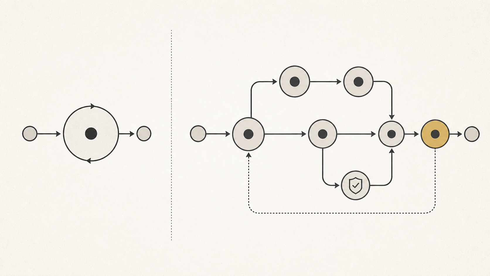 A single feedback loop is a graph; a governed topology adds branching, verification, and approval
8. Start With One Loop, Then Earn the Graph🔗
Graph engineering is not a reason to begin with a diagram containing ten agents. Begin with the smallest loop that can produce a verified result.
Add graph structure only when a real coordination pressure appears:
- Externalize state. Replace hidden conversation history with named artifacts, evidence, and budgets.
- Add an independent verifier. Separate making a result from accepting it.
- Introduce one explicit route. Add a return path for a known evidence gap or failure mode.
- Add a branch only when work is genuinely independent. Parallelism without isolation often multiplies conflicts rather than throughput.
- Name the governor. Define the human or service that owns conflict resolution and irreversible decisions.
- Measure the topology. Track where work waits, cycles, fails, escalates, and consumes budget. The graph is a system, not a slide.
This sequence produces an architecture that can grow for concrete reasons. It also preserves the practical value of simple loops: a graph should make the system easier to reason about, not turn straightforward work into organised complexity.
9. The Next Reliability Layer Is Coordination🔗
Prompting changes what a model is likely to say. Context engineering changes what it can see. Harness engineering limits what one run can do. Loop engineering makes a unit of work converge against evidence.
Graph engineering adds the missing outer structure: how several bounded work units share state, hand off artifacts, run in parallel, resolve conflict, and stop under an authority that is visible to operators.
The name may change. The underlying requirement will not. Once a system contains more than one actor, reliability depends less on the intelligence of any individual node and more on the contracts that govern their relationships.